Sunday, June 15, 2014

Final Project- Modeling Human Facial Parts 

Modeling Technique- Edge Extrusion


Basic Poly Modeling Tools:


These are your basic modeling tools that come with each geometry. In order to use these tools to do the technique, you just need to go to edge mode, select an edge you want to extend, hold your shift key and drag out. As you drag out while holding the shift key you will then have extruded your edge, while creating new geometry. You keep doing the same process over again as you build up your whole geometry.

Follow Example Step Process Below:

Start off by creating a small plane in the front view port. Set the segments to 1 for both length and width.


Now you want to right-click on your plane. Select convert to > editable poly.

Now, on the right side of the screen you will see a panel that looks similar to Fig. 3. Click on the second icon which is the modify panel.


Under the selection roll out in the modify panel, click the second icon, which is “edge.”


Now make sure you have the move and select tool selected, then select the left edge. Hold down the shift key and drag left along the x-axis (if you are still in the front viewport). 


 Congratulations, you have successfully extruded one edge of your polygon.

From here, it is a simple matter to continue extruding in whatever direction you need. At some point, however, you will need to begin to shape your object. As you shape your model and keep edge extruding you also want to keep in mind, that you are creating a whole model and that you do not want any holes or gaps, so as you go all vertices need to be welded as well.

Video on the process of edge extrusion using your basic tools:


Good tutorial on Edge Extruding geometry for the face:


Freeform Poly Modeling Tools:
The Freeform tab contains tools for creating and modifying polygon geometry by "painting" in the viewports. Also, the Defaults panel provides for saving and loading brush settings.
 
PolyDraw provides tools for quickly sketching out and editing a mesh on the main grid, projected onto the surface of another object, or on the selected object itself, depending on the Draw On setting. 

PolyDraw also provides Conform tools for molding one object to the shape of another.
The tools have different effects depending on which combination of the Ctrl, Shift, and Alt keys you press, as described in the following definitions. To exit a PolyDraw tool, click its button again or right-click in the active viewport.

Check out this website for more information on how to use these tools: Click on the Different Sections of the Tools to Learn more about each one.

 http://docs.autodesk.com/3DSMAX/15/ENU/3ds-Max-Help/index.html?url=files/GUID-2D8C6EFA-6073-4CCF-ABE7-E87FF6F0ADA0.htm,topicNumber=d30e126376


You should also check out the Digital Tutors Site on using these tools: You should have access to this through AIW school library site. You will have to go to the library site-databases- areas of study- game art and design- digital tutors- join Art Institutes Group


You will be using the edge extrusion technique to do all the modeling on your facial parts. No matter what tools you decide to use, either manually with the basic poly tools that come with your geometry or the Free Form Tools that act more like a brush, you will still be doing the same technique of Edge Extrusion.


Modeling The Human Eye with Eyelids:

   The best thing to do is model around a sphere when you start. The sphere represents the eyeball and iris. You will be modeling the eyelid and surrounding geometry. In the end, you can take the eyeball/sphere out and you will have nice form and thickness to your geometry.


To make the eye look more realistic you want to take into account the areas right next to the eyeball and the eyelids. You will find these areas right in the corners of the eye. These areas would also be considered the tear ducts of the eyes as well. You should incorporate these areas into your geometry.


When you are done with modeling the eye area it should look something like this. You can see below that the geometry forms around the eyeball and then pushes out to form the eyebrow, going into the cheek bone and then also going towards the bridge of the nose. Also notice that the geometry is clean and in quads while still keeping in the detail.


Modeling the Nose:


Monday, May 26, 2014

Mesh Typology


Next Project- Modeling a Realistic Human Foot From Reference.


Mesh Typology


Mesh Typology Topology is the layout of a model, how the vertices and edges are placed to create the mesh surface. It refers to the structure of your mesh and the way the mesh flows around the surface and details of your model. Good topology is essential if you want fast frame rates (real-time) and good deformation (both real-time and pre-rendered).

For real-time rendering, bad topology can also create rendering problems. Topology Due to the complex nature of the subject, truly understanding it and grasping how to create clean, effective topology for your models, of all subjects, can not only be daunting but also very challenging.

Examples of Human Foot Anatomy- Use this reference in how the muscles form naturally to create your edge loops and correct foot typology:


Examples of Human Foot Typology:


Reference Images Needed:


Pick one of your feet to model, either the right or the left. Next you will need a top, both sides, and a bottom image of your foot. These will be used as reference to model from. It is best if you have a friend or someone else to take the pictures. You can see from the reference, you can use a small ladder to prop up your foot.
 
After you upload your reference, you will break them up in Photoshop and make them ready for image planes in Max.


Finishing up the Unwrap for final export.

Wednesday, May 14, 2014

Examples of Unwrapping

 
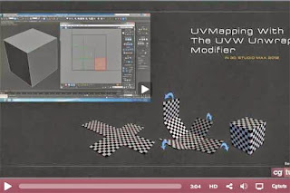
A UV layout is a visual representation of a 3D model flattened onto a two dimensional plane. Each point on the two-dimensional plane is called a UV and represents a vertex on the 3D object. In this way, all areas within the boundary of the UV layout correspond to a specific spot on the model. An easy way to visualize what a UV layout looks like is this:

Have you ever made a cube out of paper? If so, think about the shape you needed to cut into the paper in order for it to properly fold into a cube—it probably looked like a cross, four units (faces) high and three across. If that paper cube were a 3D model, every fold would be an edge, every corner would be a vertex, and every flat area would be a face. Unwrapping a model is very similar, except there are usually more than six faces to flatten.
 
Unwrapping: Unwrapping is the process of assigning each polygonal face a set of UV coordinates on the two-dimensional image plane. UV coordinates are layed out visually and exported as a square bitmap image with a resolution anywhere from 512 x 512 all the way up to 6000 pixels by 6000. The artist who paints or creates the texture maps for the model will eventually use the layout for guidance when creating the texture files.
 
 
Examples of what unwrapping a model looks like:
 
 
Examples of how your final UV gun layout should look like in the UV editor:


Tips &Tricks
 
·        Try to make all the parts of your model proportional in size to one another; you don't want a face of a character to take the same space as a button on this right pocket.
·        Whenever you stitch uv's together, you are closing seams.
·        Wherever the uv shell is open, that is where your seam will be.
·        Knowing that you will have seams, move them into places where they will be less noticeable and hidden from the viewer.
·        The best thing to think about when it comes to seams, is to think about where they would be naturally. Look at objects such as clothes, patterns, and other manufactured things for reference.
·        Use the Relax tool whenever you have any areas bunched up or to quickly clean and flatten your uv's.
·        Maximize the one by one uv space in your uv editor. Try not to leave allot of negative space.
·        If you have allot of part or pieces to your model that you are trying to unwrap and put in the same space see what you can stitch together that would make sense.
·        You do not want allot of little pieces/uv's.
·        If there are small parts that will never be seen by someone in your model, then you don't have to worry so much about them and can just unwrap them but leave them to the side. Also when you get to the point where you are packing your uv's into the one by one space, you can scale them down so that they do not take up allot of space.
·        Scale up the uv's that will need to show the most detail when it comes to texturing time. The areas of most detail on your model need to take up the most space in your uv space.
·        If you want an area on your model to have the same texture, this is the only time when you would have uv's overlap each other.